What is the DNS?
There are three levels of combustion CFD (computational fluid dynamics) approaches, depending on the ratio of the grid size to a Kolmogorov length scale of a given turbulent flow.
- RANS (Reynolds averaged Navier-Stokes)
- Grid size >> Kolmogorov length scale
- Full range of scale modeling
- Most current engineering CFD codes
- LES (Large eddy simulation)
- Grid size ~ 4-16 times Kolmogorov length scale
- Resolve ~ 80% of turbulent energy
- Need sub-grid modeling
- DNS (Direc numerical simulation)
- Grid size ~ Kolmogorov length scale
- Resolve over 99% of turbulent energy
- No modeling of turbulence closure
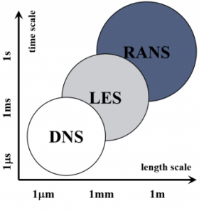
Time and lengh scales of different CFD approaches in the continuum level.
DNS of turbulent reacting flow
- Solve energy and species eqs. as well as Navier-Stokes eqs.
- Resolve the smallest turbulent length scale and flame structures
- Use realistic chemical kinetic mechanisms
- H2/air detailed mechanism: 9 species, 21 elementary reactions
- C2H4/air reduced mechanism: 22 species, 18 global reactions
- C7H16/air reduced mechanism: 58 species
- Have used the world’s most powerful supercomputer, Jaguar
- 3D DNS of turbulent lifted hydrogen jet flame in an autoignitive coflow (2008)
- 3D DNS of turbulnet lifted ethylene jet flame in a hot coflow (2009)
- DNS of ignition of n-heptane/air mixture under HCCI conditions (2010)
List of the World’s most powerful supercomputers as of Jun. 2015.
Growth of computational power and DNS capability
- Fastest supercomputer broke 33.86 Pflop/s in 2015 (Tianhe-2, China’s National University of Defense Technology) and is expected to post 1 Eflop/s in ~ 2020.
- DNS in early 1990
- 1 M grid points with 1 step chemistry
- Today’s largest DNS
- Jet Reynolds number ~ 10,000
- 1 B grid points with ~ 10 species
- Total CPU hours ~ 10 M hrs
- DNS in 2020
- Jet Reynolds number ~ 100,000
- Total CPU hours ~ 10 B hrs
Peformance of #1 (cyan), #500 (orange), and sum of all (purple), available from https://www.top500.org
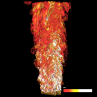
DNS of Turbulent Lifted Hydrogen/Air Jet Flame in an Autoignitive Heated Coflow
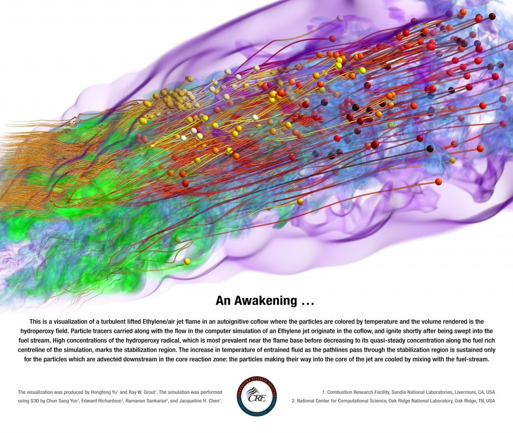
DNS of Turbulent Lifted Ethylene/Air Jet Flame in an Autoignitive Heated Coflow
3D volume rendering of perhydroxy radicals and fluid particles (This visualization was produced by Hongfeng Yu and Ray W. Grout and the simulation was performed by Chun Sang Yoo, Ed Richardson, Ramanan Sankaran, Jacqueline H. Chen)
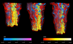
DNS of Turbulent Lifted Hydrogen/Air Jet Flames in Heated Coflows near Augo-ignition Limit
This is a visualization of turbulent lifted hydrogen/air jet flames in heated coflows near auto-ignition limit where the volume rendereds are the hydroperoxyl and hydrogen peroxide fields.
3D volume rendering of hydroxyl and perhydroxyl radicals for three different coflow temperatures (750, 850, and 950 K) (Volume rendering was performed by Prof. Yu at Univ. of Nebraska-Lincoln)
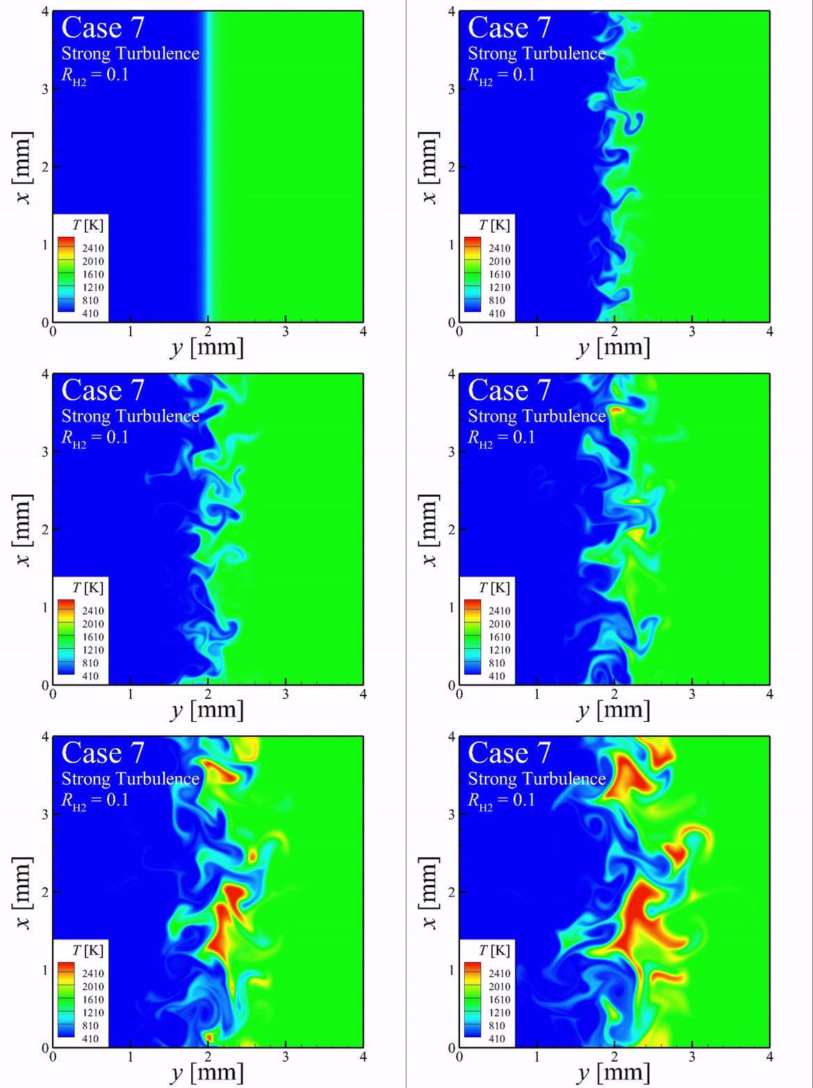
DNS of Ammonia/Air and Ammonia/Hydrogen/Air Non-premixed Ignition in Turbulent flows
Basically, ignition delay time of non-premixed mixture is advanced by turbulent flow, comparing to laminar. However, it was observed that ignition delay time is retarded at the strong turbulent intensity. And this trend is changed by the hydrogen ratio. So, it will be valuable to investigate the turbulent effect on ignition delay of non-premixed mixture having the differential diffusivity.
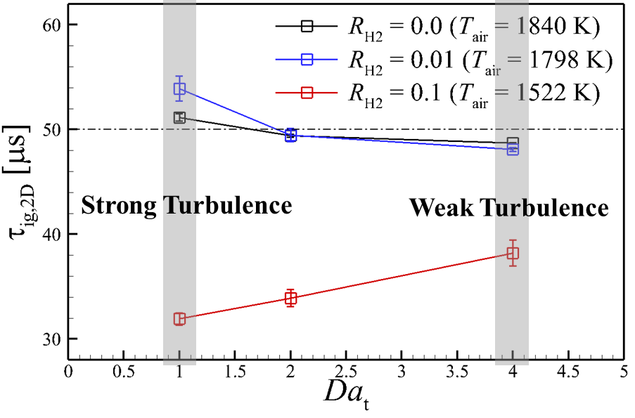
The profile of ignition delay of non-premixed mixture varied by hydrogen ratio, as a function of turbulent intensity
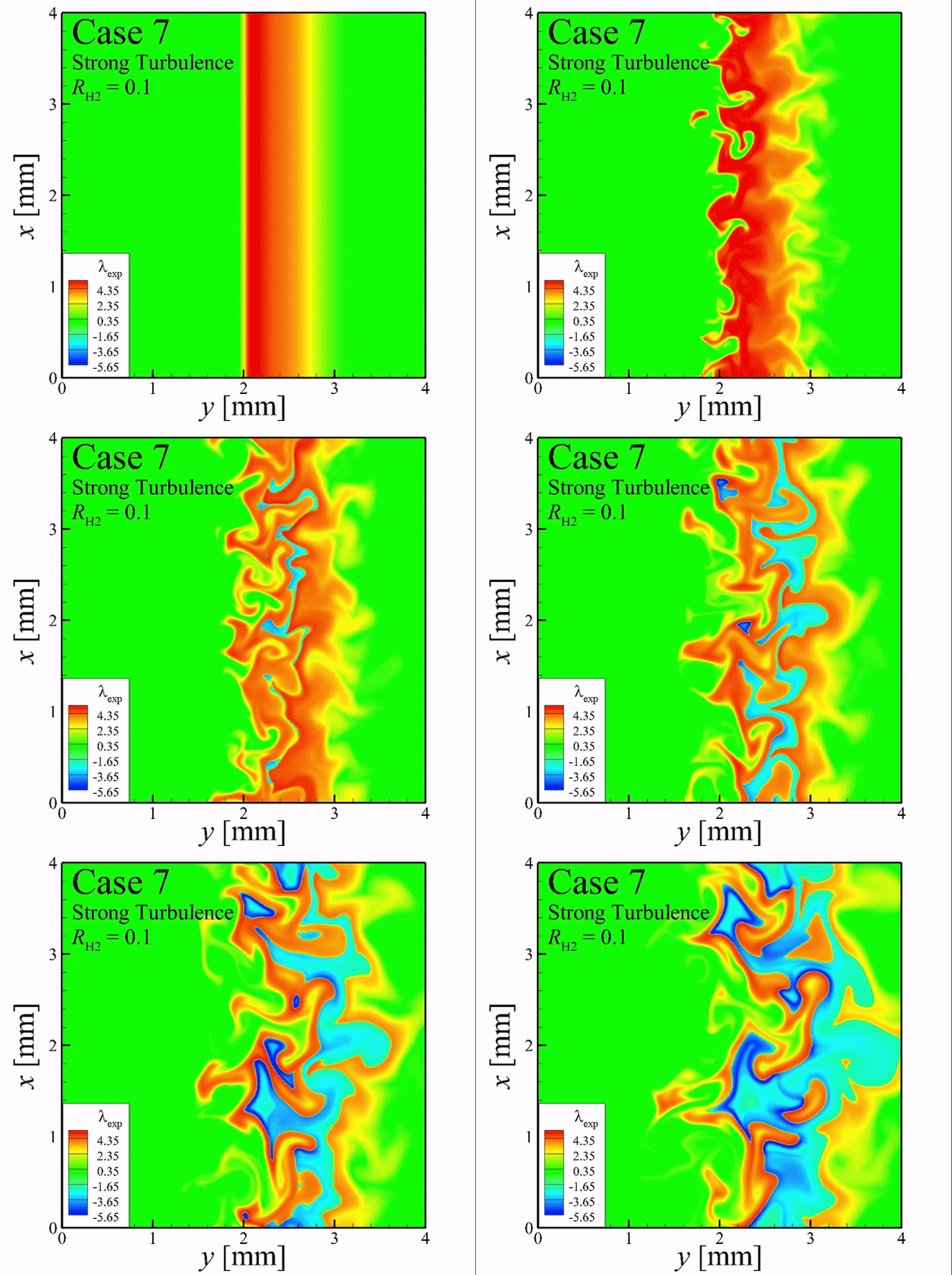
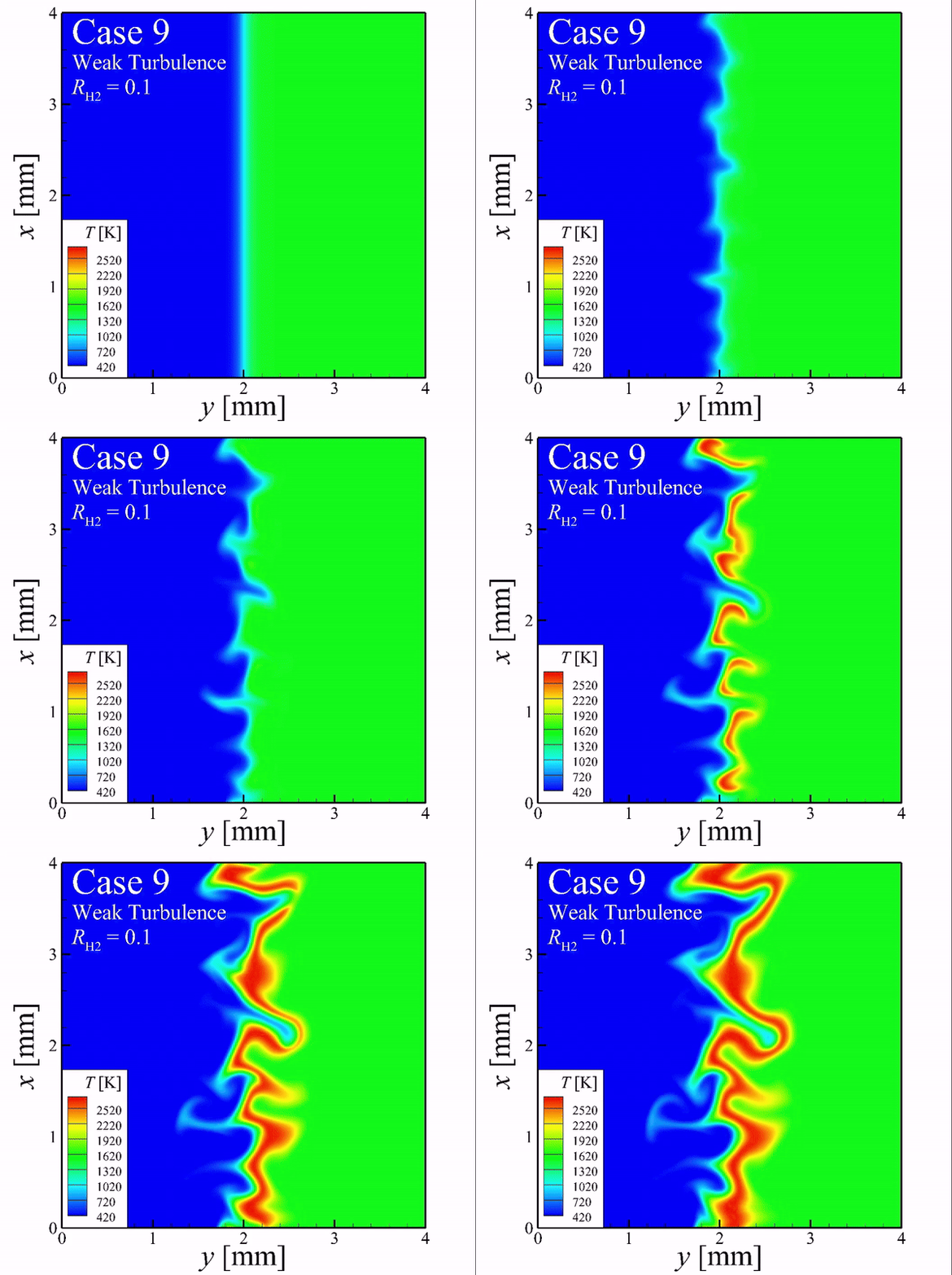
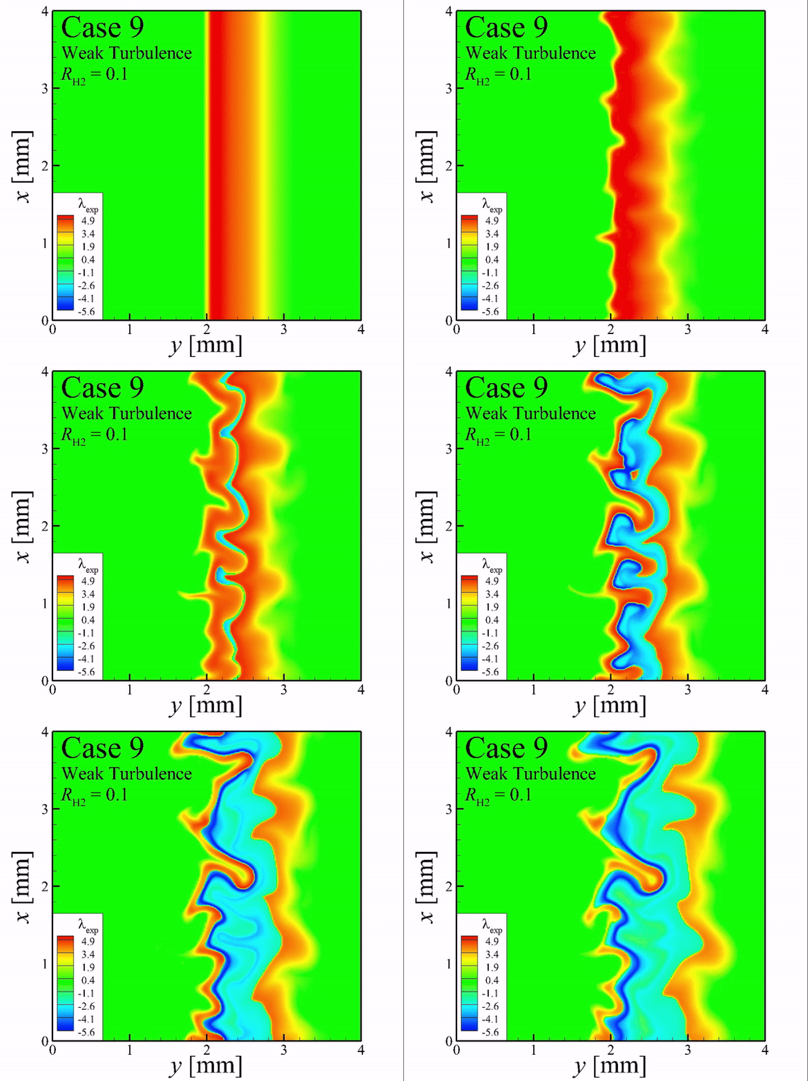
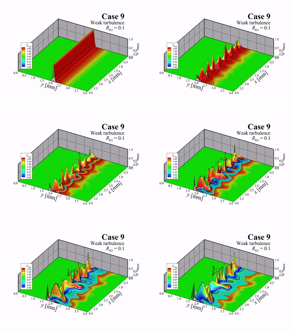
2D Iso-contour of temperature and explosive mode
Chracteristics of the flame propagation represented by the blue color according to turbulent intensity
Effect of turbulence on ignition delay time
- Variations in scalar dissipation rate of non-premixed mixture occurs in turbulence flow
- Ignition delay time of non-premixed mixture is widely varied by scalar dissipation rate
⇒ Requires a fundamental understanding of the effect of turbulence on ignition delay in the view of the variation in scalar dissipation rate
Characteristics of ignition delay time within in vortical structure
- To elucidate the non-linear profile of ignition delay according to vortex intensity
- It can be considered that turbulence is characterized by the organized motion of multiple vortex structure
-
New Findings:
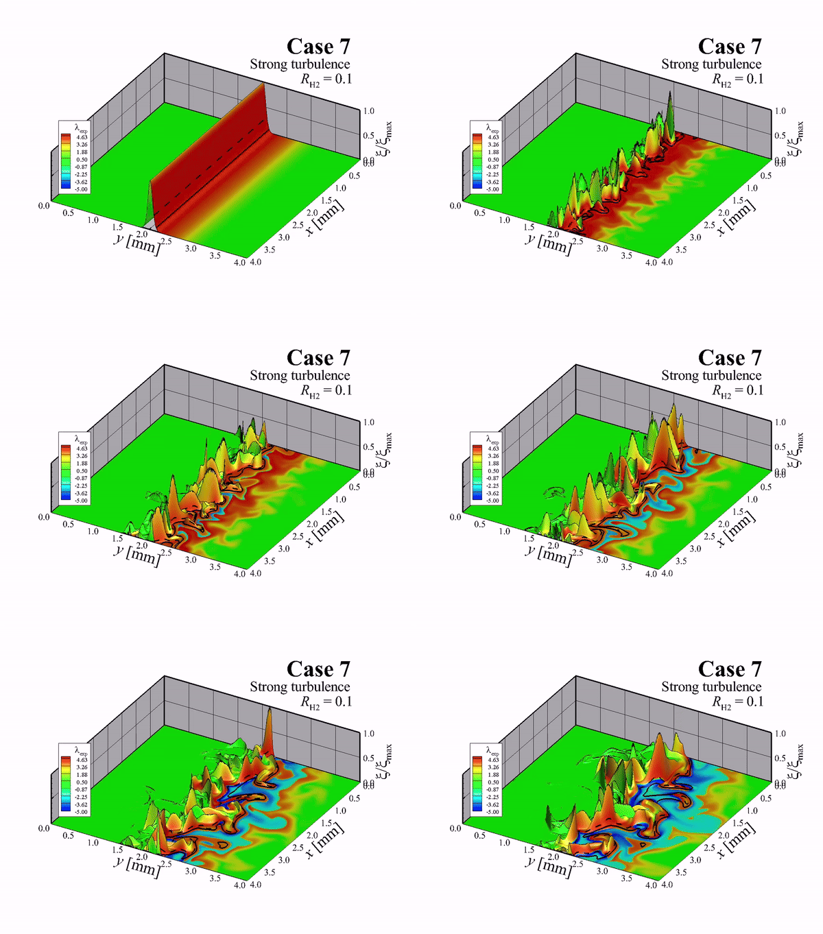
- Ignition which occurs on the vortex tip is retarded at the stroing vortex intensity.
- Advanced and ratardid effects of vortex on ignition delay can be represented by the ratio between the convective and chemical time scales.
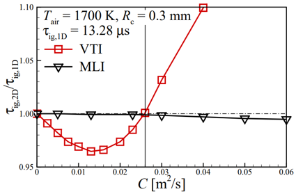
Profile of ignition delay according to vortex intensity (VTI and MLI mean the vortex tip ignition and mixing layer ignition, respectively.)
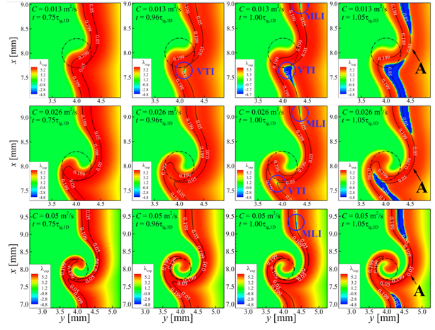
Transitional iso-contour of explosive mode indicator according to vortex intensity


